
Case 580 Shuttle Transmission Problems: The 3 Symptoms That Tell You What’s Worn
Posted by Broken Tractor on Feb 18th 2026
Shuttle slipping, no forward, or no drive at all? Rebuilding the power shuttle on a Case 480/580 series backhoe is a job a careful owner can do — but the number one reason a fresh rebuild dies young has nothing to do with the rebuild itself. It's the metal hiding in your oil cooler and torque converter. Here's the full procedure, the specs that matter, and the flush that protects your investment.
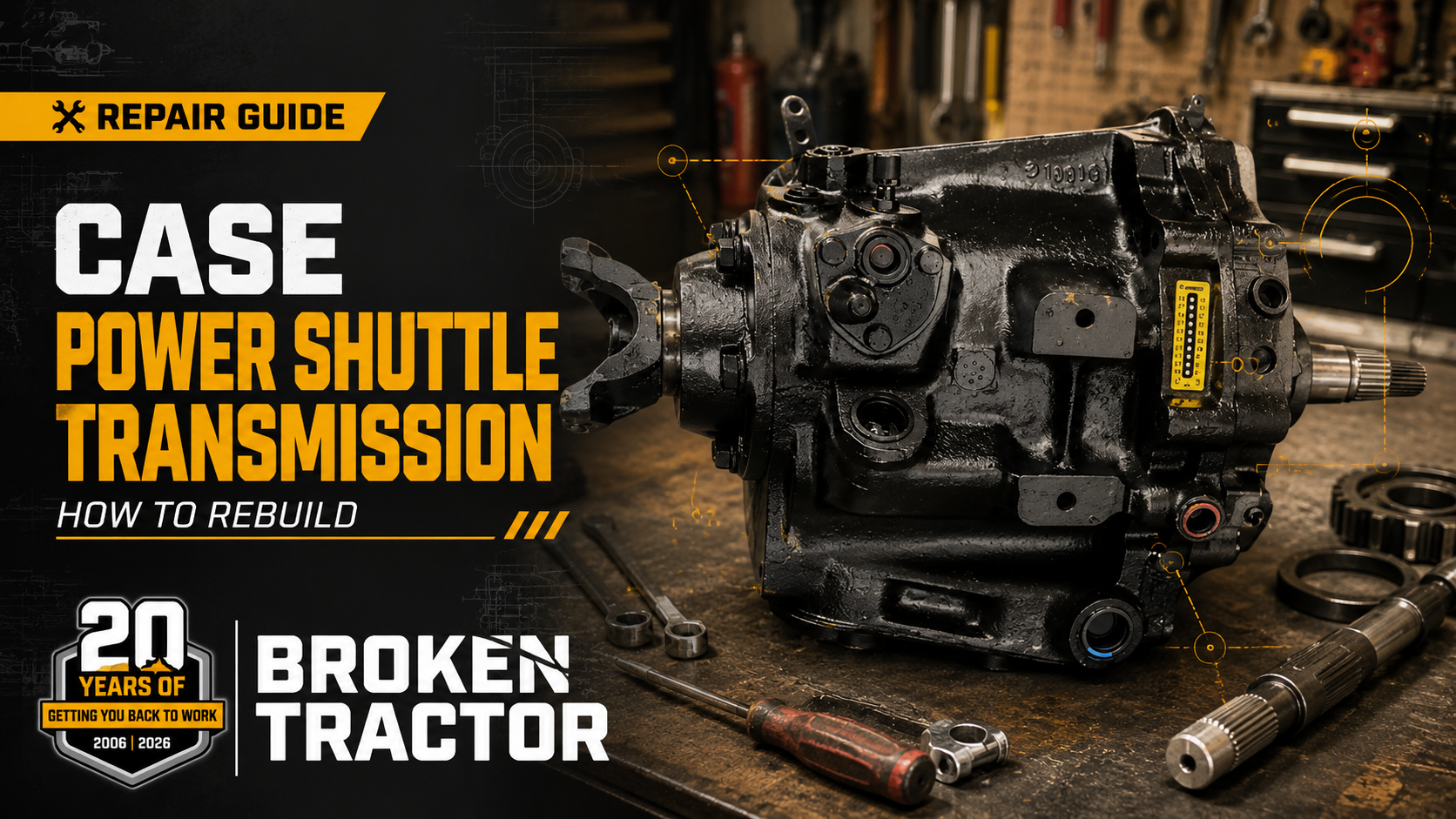
The Case power shuttle is the forward-reverse unit bolted between the torque converter and the transmission on 480 and 580 series backhoes. It's a Borg-Warner-built design — you'll hear it called the Borg-Warner shuttle, and sometimes the “Velvet Drive” shuttle after Borg-Warner's transmission line — and the same unit spans an enormous run of Case iron: 480C through 480F, 580C, 580D, 580 Super E, and 580K Phase 1 backhoes, plus the 584/585/586 forklift siblings. When it wears out, you lose forward, reverse, or both, and the fix is a rebuild: new discs, seals, bearings, and usually a new charging pump.
This guide walks the job from the Case factory service manual, Section 6210 (Power Shuttle and Torque Converter) — removal, teardown, inspection, the measurements that decide what you replace, reassembly with the factory torque specs and clutch clearances, and reinstallation. And it puts the two most important warnings in the whole job right up front, because they're the difference between a shuttle that lasts and one that comes back apart in a month.
Note on doing this job at all — A power shuttle rebuild needs a shop press, a transmission jack, snap ring pliers, a torque wrench, and patience with small parts. If that's not the winter project you had in mind, our rebuilt Case power shuttle with torque converter (DCPS) ships ready to bolt in on an exchange basis — and everything in this article about flushing the oil cooler still applies to you.
What's in this guide
- Read this first: why rebuilt shuttles fail
- How the power shuttle works
- What you'll need before you start
- Removing the power shuttle
- Teardown, in order
- Inspection: what stays and what goes
- Reassembly: the measurements that matter
- The torque converter decision
- Flushing the oil cooler and lines
- Reinstallation and torque specs
- Parts reference and kit options
Read this first: why rebuilt shuttles fail
A power shuttle rarely dies quietly. Worn clutch discs, a failing charging pump, and tired bearings shed friction material and metal into the oil — and that oil circulates through the torque converter, the oil cooler, and the cooler lines. All that debris settles in the low-flow passages of the cooler core and inside the converter, where it sits waiting.
Then you install your freshly rebuilt shuttle with its new, healthy charging pump. The new pump moves more oil at more pressure than the worn-out one ever did. It scours the cooler and converter clean — straight into your new clutch packs, bushings, and control valve. The rebuild you just did dies of the old shuttle's disease.
Two rules prevent it, and they're not optional:
Rule 1: Completely flush the oil cooler and both cooler lines before the new shuttle goes in. Not a drain — a flush, until it runs clean, in both directions. Section 9 covers how, and when a cooler should be replaced instead of flushed.
Rule 2: Replace the torque converter. The converter is a welded assembly; you cannot open it up and clean it in your driveway. Debris that entered it is still in it. We recommend a rebuilt torque converter (1995137C1) with every shuttle rebuild. If yours is being reused anyway, it must be professionally flushed on a converter-flushing machine — the same debris logic applies, and a hand rinse through the hub doesn't reach it.
This is why our shuttle parts category carries the warning in plain text: always flush the oil cooler and replace or flush the torque converter when replacing or rebuilding a power shuttle. We've seen too many good rebuilds ruined in the first fifty hours by skipping it.
How the power shuttle works
Knowing what's inside makes the teardown make sense. The aftermarket still services this unit with OEM Borg-Warner internals — the kits we sell are the same parts the unit was built with. Power flows from the engine flywheel through a flex plate into the torque converter, then into the shuttle's input shaft. A gear-type charging pump, driven off the converter, supplies oil pressure to the whole system through a suction screen in the bottom of the housing — there's no spin-on filter on these units, which is part of why debris management matters so much.
Oil leaving the torque converter flows out to the oil cooler in the bottom of the radiator and returns to the shuttle's oil pan — keep that path in mind, because it's the villain of this story. A relief valve protects the cooling circuit.
Direction is chosen hydraulically. The forward clutch is a multi-disc pack on the input shaft — seven friction discs and six metal discs: apply pressure and the input drives the output straight through. The reverse clutch works through a planetary pinion cage on the output shaft — its own disc pack (three friction discs, two metal discs) grounds the ring gear so the planetary reverses the output. A spool-type control valve with a pressure regulator directs oil to one clutch or the other, and a clutch cutout solenoid dumps pressure when you press the declutch button to shift. From the shuttle, oil circulates out through the oil cooler and back.
Symptoms map onto those parts: slipping in one direction is usually that clutch pack; slipping in both directions plus sluggish response points at the charging pump or regulator; and a shuttle that works cold but quits hot often has worn sealing rings losing pressure as the oil thins. We covered diagnosis in depth in Case 580 Shuttle Transmission Problems: The 3 Symptoms That Tell You What's Worn.
Confirm it first: the two factory pressure tests
Before you pull anything, the factory manual has two gauge tests that tell you exactly what's wrong — both run off Allen-plug test ports on the shuttle, with the oil warmed until the temp needle sits centered in the green. The numbers to know:
Test 1 — clutch circuits (0–300 psi gauge on test port 1): in neutral, the charging circuit must make at least 65 psi at low idle and 130 psi at full throttle; in forward and reverse, minimums are 60 and 125 psi. Reading the results is simple: if forward or reverse reads more than 15 psi below the neutral figure, that clutch circuit is leaking — sealing rings, supply tube, or piston seals. All six readings low together means a worn charging pump. All high means a stuck relief valve or pressure regulator.
Test 2 — cooling circuit (0–150 psi gauge on test port 2, in the adapter just ahead of the cooler return): pressure must be 40 psi or less at full throttle in neutral, forward, and reverse. Higher than 40 psi means the oil cooler is filled with dirt — the factory's words — and its fix is to remove the radiator and connecting lines and clean them. Much lower than 40 psi in neutral, with good clutch pressures, points at a damaged torque converter.
Test 2 is the number that proves everything in Section 1: a shuttle that died of worn clutches very often shows a cooling circuit already partly plugged with the debris that killed it.
What you'll need before you start
Tools and supplies
- Shop press (pressing the input shaft, clutch hub, bearings, and seals)
- Transmission jack, and a way to safely support the machine
- Snap ring pliers (heavy duty), soft-face hammer, feeler gauges, calipers
- Torque wrench covering roughly 13–85 lb-ft
- Drain pan of at least 3 U.S. gallons (11 L) — the factory spec for draining shuttle and converter together
- Compressed air (the cover piston is removed with air pressure)
- Cleaning solvent, petroleum jelly (for holding thrust washers and springs on assembly), form-in-place gasket material for the oil pan
- 8 U.S. quarts (7.5 L) of Case TCH fluid — the factory-specified oil; the shuttle holds about 2¼ quarts and the torque converter 5½
- Two alignment studs made from 7/16″-NC × 4″ cap screws with a slot cut in one end — the factory trick for guiding the shuttle onto the converter housing at installation
- Flex plate centering tool CAS-1153A — the factory tool for centering the flex plate on the torque converter at installation
- Pressure gauges (0–300 psi and 0–150 psi) if you're running the factory tests before and after
- Flushing supplies for the cooler circuit (Section 9)
Parts
The rebuild kits come in three tiers, and the right one depends on what inspection turns up — but order realistically, because the charging pump is a wear item (more on that in Section 6):
- Basic: the Case power shuttle rebuild kit (A574002) — discs, seals, and soft parts.
- Master: the master rebuild kit with pump (A574015) — the same plus a new charging pump. This is the kit we sell the most of by far, because most worn shuttles have a worn pump.
- Complete: the master rebuild kit with pump and torque converter (CS-CPSK) — everything above plus the converter, which per Rule 2 is the honest way to price this job.
Supporting parts, depending on inspection: the seal, gasket, and O-ring kit (D103220) if you're not buying a full kit, the bearing kit (D103218) covering all four shuttle bearings, a metal oil pickup filter with screen (D66455-HD) — cheap insurance given everything this article says about debris — plus, as inspection dictates: a transmission charge pump (119994A1), forward clutch piston (D70670), shuttle cylinder for 580C/580D (D50075), pinion cage and output shaft assembly (D70665), shuttle solenoid (N14766), and input shaft bearing (D50044).
Have your serial number handy — the power shuttle family spans 480C through 580K Phase 1 machines with detail changes along the way. Spool and solenoid configurations in particular vary by model and serial number — the N14766 solenoid is the late style, interchanging with D134742 and D67903. Serial number first, order second — the same rule as always. If you're not sure which transmission your machine even has, start with Case Backhoe Drivetrain Configurations.
Removing the power shuttle
The shuttle weighs about 100 pounds (45 kg) and the converter another 30 (14 kg) — respect that under a machine. The factory removal sequence, condensed:
- Apply the parking brake and block the machine securely.
- Drain the shuttle and converter. Pull the dipstick, remove the plug in the bottom of the flywheel housing, then turn the flywheel until the converter's drain plug lines up with the hole and remove it. Pull the shuttle drain plug last. Plan on 3+ gallons.
- Remove the fill tube — clamp at top, nut at bottom, then lift it out.
- Remove the drive shaft — cap screws and clamps off, shaft out.
- Disconnect the electrics and linkage — backup alarm switch wires (if equipped), neutral switch harness, parking brake buzzer wires, the shift linkage at the control arm, the clutch cutout solenoid harness, and the wire on the oil temperature gauge sender. Cut the tie strap holding the harness at the top of the shuttle.
- Disconnect the cooler hoses — bottom hose first, then top. Cap every fitting and plug every hose immediately. (You'll be flushing these lines before reassembly — but keeping grit out of them now still matters.)
- Support the shuttle on a transmission jack, remove the mounting cap screws and lock washers, work the shuttle rearward, lower it, and bring it out from under the machine.
While it's out — This is the moment to inspect the flex plate for cracks and elongated bolt holes, and to deal with the converter (Section 8). It's also the cheapest access you'll ever have to the cooler lines.
Teardown, in order
Work on a clean bench — everything in this unit is sensitive to grit. Label and photograph as you go, and mark gear positions before separating them (the charging pump gears in particular get reassembled on their original alignment marks). The factory teardown runs in this order:
- Solenoid, control arm, and detent — block the shuttle level on the bench, unscrew the clutch cutout solenoid (counterclockwise), pull the control arm and its snap ring, then remove the valve cover — the detent ball and spring live under it, followed by the detent cam. A worn detent is why a shuttle lever won't stay put, so this is a cheap fix while you're here.
- Control valve — pulls out of the housing as a unit. Set it aside for its own teardown.
- Oil pan and suction screen — unbolt the pan, lift out the screen. What you find in the pan is your damage report: friction material means discs, glitter means bushings or pump, chunks mean stop and reassess.
- Charging pump — then check end play before going deeper. Unbolt the pump from the cover and lift it off. Now put a dial indicator on the input shaft: end play must be .010–.086 inch (0.25–2.18 mm). Out of spec means worn thrust washers on the forward clutch — note it now so you order them.
- Cover assembly, reverse clutch, and internals — with the cover off, the reverse clutch comes out in layers: pressure plate, its 11 springs, then the disc pack — three friction discs and two metal discs — then the three dowel pins and the thrust washer. The forward clutch and input shaft assembly lifts out, and after the yoke nut comes off, a soft hammer drives the pinion cage and output shaft assembly from the housing.
- Bearing retainer — knocks free of the housing with a soft hammer. Behind it sits a baffle; remove it only if necessary.
- Housing needle bearing — if it's worn or damaged, measure and record its depth from the edge of the housing before pulling it. The new one goes in to that same measured depth — there's no other reference.
Then each subassembly comes apart on the bench:
- Control valve: compress the pressure regulator spring, remove the snap ring, and release the spring slowly — it's under load and will launch the seat if you let it. Spring, seat, and regulator piston out.
- Charging pump: driven gear out, then the seal pulled from the body with the body held in soft jaws. (Don't tear further — see inspection below for why.)
- Cover assembly: compressed air in the supply hole pushes the piston out of the cover. Hold the piston as it comes — air launches parts too. O-ring off the cover, quad ring off the piston.
- Forward clutch: in the press — snap ring off the ring gear, cylinder and piston pressed out, pressure plates and the disc pack out (seven friction discs, six metal discs — count them), then the input shaft pressed from the clutch hub. Woodruff key and sealing rings off the shaft, clutch spring and bearing out of the cylinder. To free the piston, use the factory trick: there are three holes in the cylinder's inner bore — cover two with your fingers and put compressed air into the third.
- Pinion cage and output shaft: disengage and remove the output shaft sealing rings. Stop before going deeper. The planetary pinion cage is closed by a collector ring that's rolled onto the cage in a lathe operation. The factory manual is blunt: before you remove it, confirm a machine shop can roll a new one on oil-tight — if not, don't open the cage; replace the pinion cage and output shaft as an assembly (D70665).
Inspection: what stays and what goes
Clean everything in solvent. Every O-ring, seal, sealing ring, and gasket is scrap — the factory manual doesn't ask your opinion on that, and neither do we; it's why the kits exist. Then inspect against the factory criteria:
Charging pump — the honest answer is usually “replace it.” The seal is the only part of the pump sold separately; damage to anything else means a new pump. And here's the trap the manual itself warns about: pump clearances are so tight that a pump can look perfect and still be too worn to make flow. A worn pump is low pressure, soft shifts, and slipping — the very symptoms you're rebuilding to fix. This is why the master kit (A574015) includes a pump, and why rebuilding around a tired original is false economy.
Clutch discs — friction and metal discs must be flat, unworn, and undamaged — check for warpage. The rule: all friction discs are replaced together, and all metal discs are replaced together. Never mix one new disc into an old pack.
Reverse clutch springs — inspect for distortion and test: 1 inch compressed length at 13.5–16.5 pounds. The pressure regulator spring tests at 2.073 inches at 74–82 pounds. Springs that don't meet spec get replaced — weak regulator spring means low system pressure everywhere.
Pistons, cylinders, pressure plates — look for pitting, scoring, and wear on the smooth faces and in the piston bores; check pressure plate teeth for damage. The cover gets the same check, plus: every oil passage clean and clear. Dowel pins checked for wear.
Bearings and bushings — pitting, scoring, or roughness means replacement; the bearing kit (D103218) covers the set.
Reassembly: the measurements that matter
Reassembly is teardown in reverse — with new soft parts throughout, clean oil on every moving part as it goes together, and four factory measurements that decide whether the shuttle works:
1. Cover bushing: 1.375–1.376 inches (34.92–34.95 mm). After the new bushing is pressed into the cover, measure its bore and ream to that window if required. A tight bushing binds the shaft; a loose one bleeds pressure.
2. Forward clutch end play: .011–.046 inch (0.28–1.17 mm). The heart of the rebuild. Build the pack in the ring gear — oiled friction and metal discs alternating, front pressure plate on — then push the pack down to close all clearance and measure between the front pressure plate and the lip of the ring gear. Select the snap ring thickness that lands the clearance in spec; they come in five sizes from .050″ to .100″. The manual's own note says it plainly: the snap ring must not completely fill the groove — without end play, the clutch can't release; with too much, it slips.
3. Housing needle bearing depth: whatever you recorded at teardown. Install the new bearing to the measurement you wrote down. (You did write it down.)
4. Pinion cage, if you opened it: 24 needle bearings per end of each pinion gear, held with petroleum jelly, spacers between; thrust plates smooth-side against the cage; the three notched pinion gears aligned with the outer shaft holes; the No. 2-marked pinion shafts pinned in first. Then the machine shop rolls on the new collector ring — oil-tight, no exceptions.
Two more snap rings in the forward clutch are fixed sizes, not select-fit — measure them: the rear pressure plate snap ring must be .090–.093 inch thick, the cylinder snap ring .074–.078 inch. When you press the cylinder and piston assembly into the ring gear, make sure the clutch spring stays seated — if it shifts out of position under the press, it will damage the cylinder. And when the ring gear goes onto the input shaft, turn the shaft until every friction disc engages: you'll know it's right when the bottom of the ring gear sits even with the bottom of the drive gear.
Beyond that: the control valve goes together with a new O-ring and the regulator spring compressed in the press to seat its snap ring (then clutch cutout spring, valve spool, a new oil seal on the plunger, and the two retaining pins driven in); the charging pump gets its new seal pressed in and the driven gear set on the alignment marks you made; the cover piston slides in on an oiled new quad ring and O-ring; thrust washers get a smear of petroleum jelly to hold them in place during assembly; and every sealing ring gets its ends properly engaged before the next part goes on.
Into the housing, in factory order: needle bearing to its recorded depth, baffle in, output shaft bearing pressed on with the housing supported in the press, new gasket, bearing retainer torqued to 40–50 lb-ft. Forward clutch into the pinion cage with drive gear, pinion, and ring gear splines aligned; thrust washer on top; three dowel pins in their slots. Then the reverse clutch, and the stacking order matters:
- Oil the discs. Friction disc first, then a metal disc — and note each metal disc has three lugs, one with an off-center groove; that lug must sit in the position the manual shows. Alternate until all three friction and two metal discs are in.
- The 11 springs into their holes in the housing.
- The pressure plate — it has a V-shaped cut, and the V must be at the top of the housing.
Then a new cover gasket, cover on with its four Ferry head screws at 27–37 lb-ft, pump gasket and charging pump at 17–22 lb-ft, suction screen in, oil pan on with form-in-place gasket material, control valve oiled and in, detent cam and ball set in petroleum jelly, detent spring in the valve cover, cover on with a new gasket, then snap ring, control arm, and the clutch cutout solenoid.
The torque converter decision
Say it again, because this is where rebuilds are won or lost: the torque converter should be replaced when the shuttle is rebuilt. The factory manual is unambiguous on the converter itself: “The torque converter cannot be repaired. If the torque converter is damaged or does not work correctly, a new torque converter must be installed.” It's a sealed, welded drum that has spent years sharing oil with the failing shuttle. Whatever the old unit shed is inside it now, and no drain-and-refill removes it. Install it behind a fresh rebuild and the new pump will pull that debris straight through your new clutch packs.
- Replace (recommended): a rebuilt Case backhoe torque converter (1995137C1) for the non-powershift machines, or the rebuilt converter (103293A1, interchanges with D81693/D71758) for the earlier units — match by serial number. Or take the decision off the table with the complete kit (CS-CPSK) that includes pump and converter.
- Reuse (only if you must): the converter has to be professionally flushed on a converter-flushing machine that circulates solvent through it under agitation until it runs clean. A garden-hose rinse through the hub is not a flush. If no shop near you offers converter flushing, that's your answer: replace it.
Flex plate note — While the converter is off, inspect the flex plate closely for cracks around the bolt holes. At installation the flex plate must be centered on the converter with tool CAS-1153A before the cap screws are tightened — a mis-centered plate vibrates, works the bolts loose, and cracks.
Flushing the oil cooler and lines
The oil cooler is the debris trap nobody sees. On these machines it lives in the bottom of the radiator, and oil leaving the torque converter passes through it on the way back to the shuttle's pan. Fine metal and friction dust ride along, and where the passages are small and the flow is calm, it settles. It sat there harmlessly while your old pump got weaker. The new pump will find it.
The factory acknowledges the problem in its own way: cooling-circuit Test No. 2 (Section 2) exists specifically “to learn if the inside of the oil cooler is filled with dirt,” and when pressure runs over 40 psi the manual's remedy is to remove the radiator and connecting lines and clean them. Our warning goes one step further, because we see what the manual's authors didn't have to warranty: a cooler doesn't have to be plugged enough to fail the pressure test to hold enough debris to kill a fresh rebuild.
Before the rebuilt shuttle goes back in:
- Flush both cooler lines individually with solvent or flushing fluid until they run absolutely clean, then blow them dry with compressed air.
- Flush the cooler core in both directions — backflush first (reverse of normal flow) to dislodge settled debris, then forward flush, repeating until what comes out is as clean as what goes in. Finish with compressed air. Pressurized flushing equipment or a dedicated cooler-flush gun does this far better than gravity.
- Judge the result honestly. If the cooler keeps producing debris after repeated flushing, if it's ever been involved in a converter or pump failure that scattered chunks (not just dust), or if flow through it is restricted, replace it. Against the cost of doing this rebuild twice, a cooler is cheap — we stock the transmission oil cooler for the 580 Super E (A171130) and transmission and hydraulic oil coolers for other Case backhoes (301239A1) — match yours by serial number.
- Install a fresh suction screen or pickup filter — the metal pickup filter with screen (D66455-HD) is the last line of defense for everything this section is about.
Why we're this insistent — This failure mode — new shuttle, old debris, dead shuttle — is the single most common reason a “bad rebuild” comes back on these machines, and it isn't a bad rebuild at all. It's a skipped flush. Every rebuilt shuttle we sell goes out with the same warning.
Reinstallation and torque specs
The factory installation has one trick worth stealing: make two alignment studs from 7/16″-NC × 4″ cap screws (cut a screwdriver slot in one end), thread one into a hole on each side of the torque converter housing, and guide the shuttle onto the studs with the jack. Then the note the manual prints in bold: do not force the shuttle into place. If it won't slide easily into contact with the converter housing, the splines aren't aligned — turn the flywheel and let it find its way. Once it's seated, run the top cap screws in, pull the studs, install the rest, and torque to 45–55 lb-ft.
Then work back through: cooler hoses (top and bottom — freshly flushed, right?), temperature sender wire, clutch cutout solenoid harness, shift linkage, buzzer and neutral switch wiring, backup alarm, drive shaft with clamps at 13–18 lb-ft, fill tube, and both drain plugs checked.
Filling it: 8 quarts of Case TCH fluid, in two stages. Pour in 3 quarts, start the engine at low idle, and immediately add the rest. Cycle the shuttle lever from forward to reverse and back several times to fill every passage, then check the dipstick with the engine at low idle and top up to the Full mark. The circuit — converter, cooler, lines — holds most of the system's oil, which is why the level plunges after first start. Shut down and check for leaks. Going forward, the factory schedule is a level check every 10 hours and an oil change with screen cleaning every 1,000 hours or yearly.
Critical torque specifications
| Fastener | Torque |
|---|---|
| Power shuttle mounting cap screws | 45–55 lb-ft (61–75 N·m) |
| Rear bearing retainer cap screws | 40–50 lb-ft (54–68 N·m) |
| Cover assembly Ferry head screws | 27–37 lb-ft (37–50 N·m) |
| Charging pump cap screws | 17–22 lb-ft (23–30 N·m) |
| Yoke | 75–85 lb-ft (102–115 N·m) |
| Flex plate to torque converter | 28–32 lb-ft (38–43 N·m) |
| Flex plate to flywheel | 13–15 lb-ft (18–20 N·m) |
| Drive shaft to yoke | 13–18 lb-ft (17–24 N·m) |
| Torque converter housing cap screws | 30–35 lb-ft (41–47 N·m) |
All values from the Section 6210 specifications page, confirmed against the complete Case 580 Super E workshop manual. One heads-up if you're following along in your own manual: the torque converter housing installation step on page 6210-19 misprints the range as “30 to 50” — the specifications page and the metric values (41–47 N·m) confirm 30–35 lb-ft. If your machine's manual shows a different value for your serial range, your manual wins.
Parts reference and kit options
| Part | Number | Fits / Function |
|---|---|---|
| Power shuttle rebuild kit | A574002 | Discs, seals, soft parts — basic rebuild |
| Master rebuild kit with pump | A574015 | Basic kit plus new charging pump — the smart default |
| Master kit with pump & torque converter | CS-CPSK | The whole job in one box |
| Rebuilt power shuttle with converter | DCPS | Exchange unit — skip the rebuild entirely |
| Rebuilt torque converter | 1995137C1 | Non-powershift Case backhoes |
| Rebuilt torque converter | 103293A1 | Interchanges D81693, D71758 |
| Transmission charge pump | 119994A1 | Case backhoe / dozer |
| Seal, gasket & O-ring kit | D103220 | 480C–F, 580C/D/Super E, early 580K |
| Power shuttle bearing kit | D103218 | All four shuttle bearings |
| Input shaft bearing | D50044 | Power shuttle input shaft |
| Oil pickup filter with screen | D66455-HD | Metal upgrade suction screen |
| Forward clutch piston | D70670 | Interchanges D50076, T101008 |
| Power shuttle cylinder | D50075 | 580C, 580D |
| Pinion cage & output shaft assembly | D70665 | Skip the collector ring gamble |
| Shuttle solenoid, late style | N14766 | Clutch cutout solenoid |
| Transmission oil cooler | A171130 | 580 Super E, angled lines |
| Transmission & hydraulic oil cooler | 301239A1 | Case backhoes — match by serial |
Full category browsing: Forward-Reverse Shuttle parts (with subcategories for kits and pumps, forward clutch, and reverse clutch), the Case backhoe torque converter category, and the full Case backhoe shuttle & transmission category. Case dozer running the same style shuttle? Start at Case dozer transmission parts.
Rebuilding the shuttle on your Case backhoe?
Rebuild kits with or without the pump and converter, rebuilt exchange shuttles, torque converters, coolers, and every hard part in between — fitment-verified for your machine and shipped from U.S. warehouses. Have your serial number handy, tell us what you found in the pan, and we'll make sure the right parts show up. And whatever you do: flush that cooler.
Broken Tractor Editorial Team
Broken Tractor LLC stocks complete power shuttle service parts for Case 480 and 580 series backhoes — rebuild kits, charging pumps, torque converters, clutch components, coolers, and rebuilt exchange units. Procedures, pressure test values, and specifications referenced in this article are drawn from the Case factory workshop manual, Sections 6202 (Power Shuttle Maintenance, Operation, and Troubleshooting) and 6210 (Power Shuttle and Torque Converter).
Keep reading
- Diagnosis — Case 580 Shuttle Transmission Problems: The 3 Symptoms That Tell You What's Worn
- Identification — Case Backhoe Drivetrain Configurations
- Serial Numbers — Case 580 Series Loader Backhoe Serial Number Guide
- Repair Guide — Case 480C, 580C & 580D Backhoe Brake Repair: Complete Walkthrough